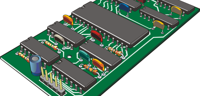
Everyone in the electronics sector has to know about the PCB manufacturing process. PCBs are commonly used to create electronic circuits. The mechanical foundation on which the circuit can be formed is provided by PCBs. As a result, printed circuit boards are utilized in every circuit, and millions of them are designed and used every year.
Track sizes are shrinking, the number of layers within the forums is increasing to accommodate the rapid connectivity required, and the design pointers are improving to accommodate smaller SMT devices. It’s possible to accommodate the soldering techniques used in production.
Printed circuit boards are the foundation of practically all electrical circuits today, but they are often overlooked. Technology in this area of electronics, on the other hand, is rapidly evolving. Track sizes are shrinking, board layers are increasing to suit the rapid connectivity required, and design requirements are evolving to ensure that production soldering procedures can be accommodated and that smaller SMT gadgets can be handled.
The PCB manufacturing process can be accomplished in a variety of ways, and there are various options. Despite minor differences, the core stage of PCB fabrication remains the same.
The fundamentals of PCB production
Following the selection and availability of bare printed circuit boards, the next step is to create the needed tracks on the board and remove any unwanted copper. A chemical etching procedure is commonly used to create PCBs. The most frequent type of etch used on printed circuit boards is ferric chloride.
A photographic approach is utilized to obtain the perfect track pattern. On bare printed circuit boards, a thin layer of photo-resist is usually employed to protect the copper. A photo-mask or photographic film detailing the needed tracks is used to expose it to light. The photo of the tracks is then placed on the photo-withstand in this manner. After that, the photo-face up to is placed in a developer so that the simplest regions of the board that require tracks are blanketed within the withstand.
The PCB boards are then immersed in ferric chloride, which is used to etch the areas where copper or track is required. It’s placed into the etch froth for the needed amount of time, knowing the ferric chloride’s attention and the thickness of the copper on the board. Because the ferric chloride tends to undercut the photo-resist if the PCB boards are left in the etch for a long time, some definition is lost.
Although photographic processing is used to manufacture the majority of printed circuit boards, other methods are also available. One option is to use a specialized milling machine that is extremely accurate. The copper is milled away from regions where it isn’t needed by the machine. The control is fully automated and is based on files generated by PCB design software. This form of PCB manufacturing isn’t suitable for huge quantities, but it’s an excellent choice for prototyping small amounts of PCBs.
PCBs with many layers
It’s becoming more difficult to provide all of the connectivity as electronic circuits become more complicated. Using only two sides of the printed circuit board, this is required. When dense microprocessors and other similar boards are being designed, this is quite common. Multilayer boards are required in this situation.
The PCB boards are constructed using thinner individual boards, one for each layer, and then glued together to create the overall printed circuit board. Individual boards must grow thinner as the number of layers increases to prevent the finished printed circuit board from becoming excessively thick. Furthermore, to ensure that any holes line up, the registration between the layers must be extremely precise.
The PCB manufacturing process is an essential part of the electronics manufacturing process. The PCB manufacturing process incorporates a wide range of modern technologies, allowing for considerable changes in component and track sizes as well as the reliability of printed circuit boards.

